First, a fluid flowing in a turbulent fashion is easier to
cool than one that is flowing in a “laminar” fashion.
“Laminar” comes from the latin phrase “flowing in layers”,
which is exactly what lube oil does. Lube oil flows in
layers, the thickness of the layers defined by the viscosity
of the oil. Higher viscosities have larger layers. The
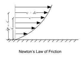
amount of energy required to mix the laminar layers can be
defined by Newton's Law of Friction as in the following
figure:
Second, to increase the ability to transfer heat from the
laminar layers to the air cooler tube wall, energy must be
added to the system in the form of pressure drop, or Delta
P. This ability to transfer heat is known as the “inside
film coefficient” of the system, or commonly seen as “Hi”
The rate of increase of Hi divided by the
increased Delta P is the “thermal efficiency” of the system.
The third key thermodynamic principle is that air coolers
are designed by balancing the amount of heat rejection
required, or Qreg, to the system’s heat rejection
capacityor Qact. Qreg is calculated as
the flow rate multiplied by the specific heat of the fluid,
multiplied by the difference between the inlet temperature,
T2 and the desired outlet temperature T1,
or:
Qreg = M*Cp*(T2-T1)
Equation for Heat Rejection Required
Qact is calculated as :
Qact = U*A*DeltaT
Equation for System’s Heat Rejection Capacity
U is the overall film coefficient of the system, A is the
required surface area, and DeltaT is the difference between
the average temperature and the ambient temperature,
corrected for type of unit [this last phrase is awkward].
Thus to properly size an air cooler, the following equation
is solved:
M*Cp*(T2-T1) = U*A*DeltaT
Equation to Properly Size an Air Cooler
As shown in the above equation, if the overall film
coefficient U is increased, the required surface area, A, of
the cooler unit can be proportionally decreased. The result
of decreasing the required surface area of the cooler unit
is significant savings - lower investment costs, smaller
space, and less energy used.
The SpiralXTM inserts, patented by Heat Exchanger
Technology, LLC, have been tested in a very controlled
laboratory environment, which included double pipe heat
exchangers where the SpiralXTM could be compared
the twisted ribbon . This test facility is shown in Figure
E.
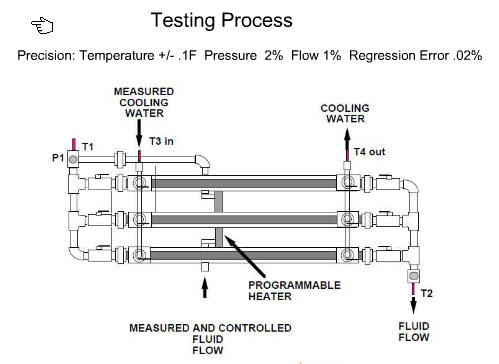
Figure E
In over 40 different tests of different turbulator designs,
the SpiralXTM inserts were the only design to
show a significant increase in the thermal efficiency of the
system by dramatically increasing the overall film
coefficient, U, of the system, thus reducing the required
surface area to cool laminar fluids, such as lube oil.
The results of the SpiralXTM test were
significant and are outlined in Figure F.
Figure F
By increasing the overall U of the system, as shown in the
Equation to Properly Size an Air Cooler, the amount of
surface area required to do the same amount of cooling for
laminar fluids can be reduced by between 140% and 150%.
A comparison of the relative number of required finned tubes
for lube oil heat transfer with SprialX inserts versus
twisted ribbon inserts is shown below:
This
illustration shows that for lube oil cooling services in air
coolers, four (4) 1" SpiralX finned tubes will transfer the
same amoutn of heat as twelve (12) 5/8" finned tubes with
twisted ribbons. Comprehensive test data verifying the
comparison is available upon request.
With SpiralX TM inserts, the reduction in size of
the air coolers also allows packagers to provide units that
meet the requirements of the A.S.M.E. Code for U fired
pressure vessels at an affordable price. This “U” stamp is
increasingly demanded by end users, similar to the way
reciprocating compressor packages have been packaged for
decades. With SpiralX TM inserts, there is no
longer a need for using aluminum radiators or soldered
joints in an environment they were never designed for in the
first place.
To meet the requirements necessary to label the SpiralXTM
air coolers as “green”, Heat Exchanger Technology
added another design feature that is new to the natural gas
industry but proven technology for HVAC systems, water
chillers, and refrigeration systems. Instead of one enormous
fan blowing air across the coils 24/7, 365 days a year,
multiple, small efficient fans are used which are turned on
and off based on the load required by the system.